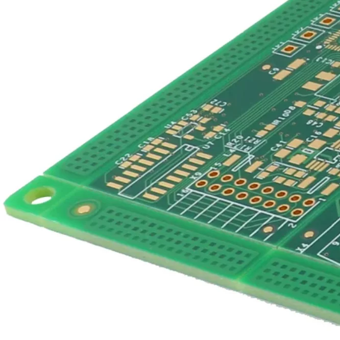
Printed circuit boards are fundamental to modern electronic systems, providing the electrical connections and physical support required for components to function together. However, different applications place different demands on PCB materials, signal transmission, thermal performance, and manufacturing precision.
Radio frequency (RF) circuit boards are designed for applications where high-frequency signals must travel with controlled impedance and minimal electrical loss. Standard FR-4 PCBs, on the other hand, are widely used because of their affordability, mechanical strength, and versatility across general electronic applications.
Although both types serve as platforms for electronic circuits, their material properties and design requirements can differ considerably. Understanding the differences between RF circuit boards and standard FR-4 PCBs helps engineers select an appropriate board construction for their operating frequency, performance targets, and project budget.

What Are RF Circuit Boards?
RF circuit boards are printed circuit boards engineered to transmit and receive radio-frequency signals while maintaining predictable electrical characteristics. They are used in wireless communication systems, radar equipment, antenna assemblies, satellite technology, and other applications where signal loss and impedance variation must be carefully controlled.
RF applications can operate across a wide range of frequencies, from relatively low radio frequencies to microwave and millimeter-wave bands. The appropriate PCB material depends on the specific operating frequency, signal bandwidth, power level, and performance requirements rather than a single universal frequency threshold.
Compared with general-purpose PCB designs, RF boards typically require closer coordination between material selection, transmission-line geometry, grounding structures, and electromagnetic compatibility. These factors help reduce unwanted reflections, excessive attenuation, and interference that could affect circuit performance.
Characteristics of RF Circuit Boards
1. Material Selection
RF PCB materials are selected according to their dielectric constant, dissipation factor, thermal behavior, and dimensional stability. Low-loss laminates, including PTFE-based materials and specialized high-frequency laminates from manufacturers such as Rogers, are commonly considered for demanding RF applications.
These materials can reduce dielectric losses and support more predictable signal propagation at high frequencies. The best choice depends on the electrical requirements, layer structure, manufacturing process, and total cost of the design.
2. Impedance Control
Maintaining the intended characteristic impedance is essential for RF signal transmission. Variations in trace width, dielectric thickness, copper geometry, or material properties can cause impedance discontinuities and unwanted signal reflections.
RF PCB designs therefore require careful control of transmission-line dimensions and stack-up parameters. Ground-plane configuration, copper thickness, and the dielectric properties of the selected laminate must also be considered to achieve the target impedance.
3. Low Signal Loss
High-frequency signals can lose energy as they travel through PCB conductors and dielectric materials. Conductor roughness, copper resistance, dielectric dissipation, and transmission-line geometry all contribute to overall insertion loss.
RF circuit boards use suitable low-loss materials and optimized routing structures to reduce these effects. Proper layout practices, controlled trace geometry, and appropriate grounding also help preserve signal quality across the intended frequency range.
4. Thermal Management
RF components, power amplifiers, and other high-frequency devices can generate significant heat, particularly in high-power applications. Excessive temperatures may affect electrical characteristics, component life, and system stability.
Thermal management strategies may include copper planes, thermal vias, heat spreaders, heatsinks, and thermally suitable substrate materials. The required solution depends on component power dissipation, board construction, and the available heat-transfer paths.
5. EMI Shielding
Electromagnetic interference (EMI) can disrupt RF circuits or cause unwanted emissions that affect nearby electronic systems. PCB designers may use continuous ground planes, shielding enclosures, grounded partitions, filtering networks, and carefully controlled routing to manage electromagnetic coupling.
The shielding approach should match the frequency range, circuit sensitivity, and system-level electromagnetic compatibility requirements. Good grounding and layout design are essential because shielding alone cannot eliminate every source of interference.
Applications of RF PCBs
The electrical characteristics of RF circuit boards make them suitable for a variety of communication, sensing, and high-frequency signal-processing systems.
1. Telecommunications: RF PCBs are widely used in cellular infrastructure, wireless transceivers, antenna systems, and satellite communication equipment. Their controlled electrical characteristics help maintain signal quality in systems that transmit and receive information across designated frequency bands.
2. Radar Systems: Radar equipment relies on radio-frequency signals to detect objects, measure distances, and determine movement. RF circuit boards support signal generation, transmission, reception, and processing in applications such as weather monitoring, aviation, industrial sensing, and defense systems.
3. Wireless Communication Devices: Wi-Fi routers, Bluetooth equipment, wireless access points, and other connected devices use RF circuitry to communicate through radio waves. Appropriate PCB materials and layout techniques help maintain the performance of antenna feeds, filters, amplifiers, and transceiver circuits.
4. Medical Devices: RF circuit boards are used in selected medical imaging, wireless monitoring, diagnostic, and therapeutic equipment. In these applications, predictable signal transmission and electrical stability can be important for measurement accuracy and system performance. Specific requirements depend on the device type and applicable medical standards.
5. Automotive Electronics: Modern vehicles incorporate RF circuitry in radar-based driver assistance systems, wireless connectivity, navigation, keyless entry, and vehicle communication equipment. These applications may require stable electrical performance across broad temperature ranges and under challenging operating conditions.
What are Standard FR-4 PCBs?
FR-4 is a widely used PCB base material consisting primarily of woven glass-fiber reinforcement bonded with epoxy resin. The designation refers to a recognized flame-retardant material classification rather than simply identifying the fourth generation of a material.
Standard FR-4 PCBs are valued for their mechanical strength, electrical insulation, broad availability, and cost-effectiveness. They are used in consumer electronics, industrial controllers, automotive electronics, computing equipment, instrumentation, and numerous other electronic products.
FR-4 is available in different material grades and formulations, with variations in dielectric properties, thermal performance, and moisture resistance. While conventional FR-4 is suitable for many low- and moderate-frequency designs, its electrical losses and dielectric variability can become important considerations as operating frequencies and signal-speed requirements increase.
Characteristics of FR-4 PCBs
1. Material Properties
FR-4 provides a stable structural foundation for mounting components and forming copper circuit patterns. Its glass-fiber reinforcement contributes to mechanical strength, while the epoxy resin system provides electrical insulation.
However, its dielectric constant and dissipation factor depend on the specific laminate formulation, frequency, temperature, and test conditions. Some FR-4 grades can support demanding digital designs, but conventional grades may exhibit greater dielectric loss than specialized RF laminates at higher frequencies.
2. Cost-Effectiveness
One of the main advantages of FR-4 is its favorable balance between performance and manufacturing cost. It is widely available and supported by established PCB fabrication processes, making it suitable for large-volume production.
For many projects, FR-4 provides sufficient electrical and mechanical performance without the additional material costs associated with specialized high-frequency laminates. This makes it an economical choice when RF-level loss requirements are unnecessary.
3. Versatility
FR-4 can be used in a wide range of single-layer, double-layer, and multilayer PCB constructions. It supports applications ranging from simple control circuits to complex digital systems, depending on the selected material grade and design parameters.
Nevertheless, its suitability must be evaluated against the actual signal frequency, transmission distance, insertion-loss budget, and impedance requirements. Higher-frequency or particularly low-loss applications may benefit from specialized laminate materials or hybrid PCB constructions that combine different dielectric materials.
4. Thermal Performance
FR-4 provides adequate thermal performance for many conventional electronic assemblies, but its thermal conductivity is relatively low compared with copper and many specialized thermal-management materials.
Heat generated by power components must therefore be managed through suitable copper distribution, thermal vias, component placement, heatsinks, and enclosure design. Applications with high power density or demanding thermal requirements may need additional design measures or alternative substrate materials.

Key Differences Between RF PCBs and Standard FR-4 PCBs
RF circuit boards and standard FR-4 PCBs differ primarily in their material requirements, signal transmission characteristics, manufacturing controls, and intended applications. The most appropriate option depends on the performance targets of the complete electronic system.
1. Material Composition and Properties
RF PCBs: RF designs frequently use specialized low-loss laminates, including PTFE-based materials and selected high-frequency hydrocarbon or ceramic-filled materials. These laminates are chosen for their dielectric characteristics, loss performance, and stability across the intended operating conditions. Some RF designs can also use suitable FR-4 grades when their electrical requirements permit it.
Standard FR-4 PCBs: Conventional FR-4 uses glass-fiber reinforcement and epoxy resin to provide mechanical support and electrical insulation. Its cost and versatility make it a common choice for general electronics. However, material loss and dielectric-property variation may limit its suitability for applications with particularly demanding high-frequency performance requirements.
2. Impedance Control
RF PCBs: RF circuit designs often require precise control of characteristic impedance to reduce reflections and maintain consistent signal transmission. Trace dimensions, dielectric thickness, copper properties, grounding structures, and the selected laminate must be coordinated carefully. Manufacturing tolerances can have a direct effect on electrical performance, especially at microwave and millimeter-wave frequencies.
Standard FR-4 PCBs: FR-4 boards can also be designed with controlled impedance, including applications such as high-speed digital interfaces and RF circuits with moderate requirements. However, achieving the required impedance depends on the material grade, stack-up consistency, fabrication tolerances, and the frequency-dependent properties of the laminate. Standard FR-4 is not inherently incapable of impedance control; suitability depends on the design specifications.
3. Signal Integrity
RF PCBs: RF designs focus on maintaining predictable signal behavior across the intended frequency range. Low-loss materials, optimized transmission lines, appropriate grounding, and careful management of discontinuities help reduce attenuation and reflections. Other factors, including conductor roughness, connector transitions, and electromagnetic coupling, must also be considered.
Standard FR-4 PCBs: FR-4 provides acceptable signal integrity for many general electronic and digital applications. As frequency and transmission distance increase, dielectric and conductor losses may become more significant, depending on the selected material grade and design. Engineers should evaluate the complete signal path to determine whether standard FR-4 meets the insertion-loss and signal-quality requirements.
4. Thermal Management
RF PCBs: Thermal management is especially important in RF power amplifiers, transmitters, and other circuits with concentrated heat sources. Designers may integrate copper planes, thermal vias, heatsinks, or specialized substrate materials to transfer heat away from critical components. The thermal solution depends on power dissipation and the overall PCB structure, rather than being determined solely by the RF designation.
Standard FR-4 PCBs: FR-4 is suitable for many electronic products with moderate thermal demands. However, its relatively low thermal conductivity can make heat spreading more challenging in high-power or densely populated circuits. Appropriate copper layouts, thermal vias, and external cooling structures can help address these limitations.
5. Cost and Complexity
RF PCBs: Specialized RF laminates can be more expensive than conventional FR-4 materials. Additional design analysis, tighter dimensional tolerances, controlled material handling, and specialized testing may also increase manufacturing costs. These expenses can be justified when the application requires low signal loss, stable high-frequency performance, or demanding electrical tolerances.
Standard FR-4 PCBs: FR-4 boards generally offer lower material costs and broad manufacturing availability. They are suitable for many high-volume consumer, industrial, and commercial products. When the electrical requirements can be met with conventional FR-4, this material can provide an effective balance between manufacturing cost and performance.
6. Applications
RF PCBs: Typical applications include wireless communication infrastructure, radar equipment, satellite systems, RF front-end modules, antenna circuits, and high-frequency sensing devices. These designs benefit from carefully selected dielectric materials and controlled transmission-line structures.
Standard FR-4 PCBs: FR-4 is commonly used in consumer electronics, digital control systems, instrumentation, power management circuits, industrial automation, and a broad range of automotive and computing products. It is especially suitable when its electrical, thermal, and mechanical properties satisfy the system requirements at a competitive cost.
RF PCBs vs Standard FR-4 PCBs at a Glance
Comparison Factor | RF Circuit Boards | Standard FR-4 PCBs |
Base Material | Often specialized low-loss laminates | Glass-fiber-reinforced epoxy |
Dielectric Loss | Typically optimized for low-loss transmission | Depends on the FR-4 grade; conventional grades may have higher losses |
Impedance Control | Often requires tight control for RF performance | Achievable when the stack-up and fabrication process are appropriately specified |
High-Frequency Performance | Designed for demanding RF and microwave applications | Suitable when the selected grade meets the frequency and loss requirements |
Thermal Management | May use specialized materials and engineered heat-transfer structures | Often relies on copper planes, thermal vias, and external cooling |
Manufacturing Cost | Often higher due to materials and process requirements | Generally more economical and widely available |
Typical Applications | Radar, antennas, RF modules, wireless infrastructure | Digital electronics, industrial controls, consumer products, general electronics |
Conclusion
RF circuit boards and standard FR-4 PCBs serve different engineering needs, although their capabilities can overlap depending on the material grade and design requirements. RF PCBs are typically developed for applications that demand predictable high-frequency transmission, low signal loss, and carefully controlled electrical characteristics. Standard FR-4 remains a practical and economical option for a wide range of general-purpose and digital electronic systems.
Choosing between these PCB types requires an assessment of operating frequency, insertion loss, impedance requirements, thermal conditions, mechanical constraints, and manufacturing budget. Rather than selecting a material based on frequency alone, engineers should evaluate the electrical properties of the complete PCB stack-up and verify that it meets the intended performance targets.
Working with an experienced PCB manufacturer during the design stage can help identify suitable materials, optimize the layer structure, and balance performance against production cost. With the right material selection and fabrication controls, engineers can develop circuit boards that meet application-specific requirements while maintaining reliable operation and manufacturing consistency.